
Effective Date: April 1, 2026
Summary: This standard specifies the technical requirements, construction procedures, and quality assessment methods for using high-speed hydraulic compactors on road subgrades. It primarily provides engineering guidance for reinforcement compaction in areas where traditional rollers struggle to achieve full density—such as bridge/culvert approaches, transitions between old and new roads, high embankments, and deep fills—ensuring subgrade stability and minimizing post-construction settlement.
Standard of China Association for Engineering Construction Standardization
高速液压夯实路基技术规程
T/CECS 2060-2025
Chief Drafting Organizations: Shandong Transport University Shandong Jinyue Transport Development Group Co., Ltd.
Approved by: China Association for Engineering Construction Standardization
Effective Date: April 1, 2026
China Architecture & Building Press 2025 Beijing
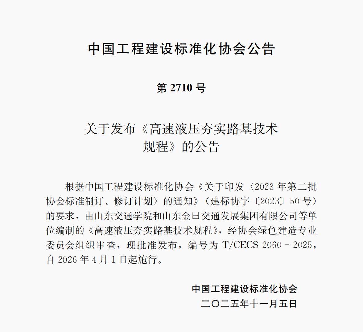
No. 2710
Announcement on the Publication of Technical Specification for Rapid Impact Compaction of Subgrade
In accordance with the requirements of the Notice on Printing and Distributing the 2023 Second Batch of Association Standard Formulation and Revision Plan (Jian Biao Xie Zi [2023] No. 50) of the China Association for Engineering Construction Standardization, the Technical Specification for Rapid Impact Compaction of Subgrade drafted by Shandong Transport University, Shandong Jinyue Transport Development Group Co., Ltd. and other organizations has been reviewed and approved by the Green Construction Professional Committee of the Association, and is hereby published as T/CECS 2060-2025, effective from April 1, 2026.
China Association for Engineering Construction Standardization
November 5, 2025
The Technical Specification for Rapid Impact Compaction of Subgrade (hereinafter referred to as the Specification) has been prepared in accordance with the requirements of the Notice on Printing and Distributing the 2023 Second Batch of Association Standard Formulation and Revision Plan (Jian Biao Xie Zi [2023] No. 50) of the China Association for Engineering Construction Standardization. The drafting team has conducted in-depth investigation and research, earnestly summarized practical experience, referred to advanced domestic and international standards, and formulated this Specification on the basis of extensive solicitation of opinions.
This Specification consists of 5 chapters and 2 appendices, covering: General Provisions, Terminology, Basic Requirements, Construction, and Quality Inspection.
Some contents of this Specification may directly or indirectly involve patents. The publishing body of this Specification does not assume the responsibility for identifying such patents.
This Specification is under the centralized management of the Green Construction Professional Committee of the China Association for Engineering Construction Standardization, and Shandong Transport University is responsible for the interpretation of specific technical contents. During implementation, any comments or suggestions shall besubmitted to Shandong Transport University (Address: No. 5001 Haitang Road, University Science and Technology Park, Changqing District, Jinan, Shandong Province; Postal Code: 252357; Tel: 0531-80687910; Email: 772002882@qq.com).
Chief Drafting Organizations: Shandong Transport University, Shandong Jinyue Transport Development Group Co., Ltd.
Participating Drafting Organizations: CCCC First Highway Engineering Group Co., Ltd., Tai'an Hengda Machinery Co., Ltd., Shandong Taiyu Geotechnical Engineering Co., Ltd., Shandong Yimeng Transport Development Group Co., Ltd.
Chief Drafters: Li Jin, Zuo Tuan, Cui Xinzhuang, Xiong Dalu, Yuan Kai, Cheng Degang, Lu Zhongmei, Peng Nannan, Qiao Tianfei, Liu Tao, Zhao Yanlei, Zhao Liandi, Bi Junwei, Li Qingluan, Zhang Menghan, Wang Xianwei, Zhang Sibo, Xu Meng, Li Hongzhen, Sun Chengyin
Chief Reviewers: Sun Jie, Liu Zhi, Guo Baoning, Fu Jiancun, Liu Guohui, Wang Xiangen, Chen Degang
1.0.1 This Specification is formulated to standardize the application of Rapid Impact Compaction (RIC) technology for subgrade, improve the technical level of RIC subgrade construction, and ensure safety, economy, and engineering quality.
1.0.2 This Specification applies to the construction and quality inspection of RIC technology for highways and urban roads.
1.0.3 The application of RIC technology for subgrade shall comply not only with this Specification but also with the provisions of current national standards and current standards of the China Association for Engineering Construction Standardization.
2.0.1 Rapid Impact Compaction (RIC)
A construction method that utilizes the impact energy of a Hydraulic Impact Hammer converted into dynamic pressure energy to compact Foundation Soil at a frequency of no less than 30 blows per minute.
2.0.2 Effective Improvement Depth
The depth at which the subgrade strength or improvement indices after compaction meet the design requirements.
2.0.3 Single-Blow Impact Energy
The impact energy possessed by the hammer when driven by the effective stroke of the hydraulic cylinder.
2.0.4 Number of Blows
The cumulative number of blows applied to a single Impact Point, either continuously or in passes.
2.0.5 Number of Passes
The number of passes when compaction is carried out in multiple passes, or when alternate-row or alternate-point compaction methods are adopted.
2.0.6 Point Layout Spacing
The distance between adjacent Impact Points arranged within the Ground Improvement area.
2.0.7 Impact Point Spacing
The distance between Impact Points during compaction operations.
2.0.8 Point Compaction
A compaction procedure in which concentrated and continuous compaction is applied to individual Impact Points pre-arranged within the Ground Improvement area using high-energy impact energy.
2.0.9 Blanket Compaction
A method of final treatment of the subgrade surface using energy lower than that of Point Compaction.
2.0.10 Single Impact Cycle
A working process in which the Hydraulic Impact Hammer is lifted once and then dropped to complete a single impact.
2.0.11 Impact Frequency
The number of impacts completed by the Rapid Impact Compactor (RIC Equipment) per unit of time.
2.0.12 Average Compaction Settlement
The difference in average elevation of the site before and after compaction.
2.0.13 Tamper Foot Diameter
The diameter of the base plate at the lower part of the hammer that contacts the subgrade soil.
2.0.14 Interval Between Passes
The time interval between two successive compaction passes.
2.0.15 Waiting Period Before Testing
The time interval between the completion of compaction and the commencement of testing.
3.0.1 RIC is suitable for Foundation Soil such as gravel fill, miscellaneous fill, plain fill, silt, general cohesive soil, and collapsible loess.
3.0.2 The technical requirements for Degree of Compaction and Subgrade after compaction, Effective Improvement Depth, treatment range, post-compaction testing methods, and quantities shall be determined based on the soil type of the subgrade to be improved, the load of buildings or structures, the type of foundation, and the surrounding environmental conditions.
3.0.3 When construction vibrations may affect adjacent buildings or structures, precision instruments and equipment, or engineering structures under construction, the impact of vibration on the surrounding environment shall be assessed, the safe construction distance shall be defined, vibration reduction measures shall be taken, and monitoring points shall be set up when necessary.
3.0.4 Trial compaction shall be conducted before construction. The number of trial compaction zones shall be determined according to the complexity of the site, the scale and type of the building, and the area of each zone shall not be less than 100 m². Alternatively, trial construction may be carried out to verify the applicability of process parameters and the treatment effect, and the construction plan shall be optimized accordingly.
3.0.5 Before construction, the site and surrounding environment shall be investigated to identify the locations and burial depths of underground structures and pipelines, and exploration for damage prevention shall be conducted when necessary. The elevation of the starting compaction surface shall be determined based on the designed foundation base elevation, the estimated settlement, and the thickness of the protective layer.
3.0.6 When the groundwater level is high, measures to lower the groundwater level shall be taken. The groundwater level shall be no less than 1.5 m below the starting compaction surface.
3.0.7 For highly saturated cohesive soil, construction shall preferably adopt the method of filling materials in the compaction pit or replacing with a coarse-grained cushion layer.
3.0.8 For subgrade in special sections, geological survey data shall be verified first to confirm the consistency between design data and actual conditions and the applicability of the treatment method. When necessary, supplementary geological and hydrological surveys shall be conducted, and the treatment plan shall be re-determined based on the results.
3.0.9 The construction of RIC subgrade shall strengthen quality control and management, meet engineering design requirements, and comply with the principles of adapting to local conditions, using local materials, conserving resources, and protecting the environment.
4.1.1 Before construction, the locations and burial depths of above-ground and underground buildings or structures and various underground pipelines inside and outside the site shall be identified, and effective protective measures shall be taken when necessary.
4.1.2 For miscellaneous fill, plain fill, sand, and gravel fill with shallow improvement depth, construction may be carried out using one pass each of Point Compaction and Blanket Compaction. For fill, collapsible loess, silt, and cohesive soil with deeper improvement depth, construction may adopt the alternate-point or alternate-row method. For cohesive soil with high water content, multiple passes of Point Compaction shall be adopted.
4.1.3 Before operating the Rapid Impact Compactor (RIC Equipment), the Hydraulic System and components shall be inspected. Operations shall follow the sequence of no-load before load, and slow speed before fast speed. Personnel shall receive professional training and wear safety equipment. Warning signs shall be posted in the construction area. The distance between the Rapid Impact Compactor (RIC Equipment) and the wall shall not be less than 0.3 m. After compaction, the surface loose soil shall be removed, and the Degree of Compaction shall be verified using the sand replacement method.
4.1.4 Before RIC construction, a special construction plan shall be prepared to specify key parameters such as Point Layout, impact energy level, Number of Blows, and Interval Between Passes, and technical briefing shall be conducted.
4.2.1 The main technical parameters of the Hydraulic Impact Hammer shall comply with the provisions of Table 4.2.1.
Table 4.2.1 Main Technical Parameters of Hydraulic Impact Hammer
(Note: The original table is in image format. Specific parameters include: Single-Blow Impact Energy classifications of light type 12~30 kJ, medium type 36~84 kJ, and heavy type 108 kJ and above, along with corresponding ranges for hammer mass, tamper foot diameter, and impact frequency.)
4.2.2 The Rapid Impact Compactor (RIC Equipment) shall preferably be used in conjunction with a Hydraulic Excavator, crawler crane, Wheel Loader, or other specialized equipment. The Carrier Machine power shall be selected according to the impact energy, and the pressure and flow of the Carrier Machine's Hydraulic System shall meet the requirements for driving the Hydraulic Impact Hammer. The model and power of the Carrier Machine shall be compatible with the total weight, rated pressure, and flow of the Hydraulic Impact Hammer.
4.3.1 Construction shall proceed in the following steps:
1 Mark the Impact Point locations according to the designed Point Layout diagram, position the Rapid Impact Compactor (RIC Equipment), and align the hammer centerline with the Impact Point center;
2 Start the hammer and complete the compaction of a single Impact Point according to the designed Number of Blows and control requirements; when the compaction pit is deep but without obvious heave and the stopping criteria have not been met, the pit may be filled level and compaction continued, and the cumulative Number of Blows shall be recorded;
3 Move to the next Impact Point and repeat the procedure of Item 2 of this clause until all Impact Points have been compacted;
4 Fill the compaction pits with a bulldozer and apply Blanket Compaction at no less than 1/2 of the Point Compaction energy, and measure the site elevation;
5 After the specified interval, repeat the procedures of Items 2 through 4 successively to complete all compaction passes;
6 After construction, measure the Average Compaction Settlement of the site area.
4.3.2 Impact Points shall be arranged in triangular or square patterns with a spacing of 1.5 to 2.0 times the tamper foot diameter. Blanket Compaction shall be no less than 6 to 9 blows, and the overlap of the tamper foot shall be greater than 1/4 of its diameter.
4.3.3 For weak soil layers, the initial hydraulic cylinder stroke should be small and gradually adjusted to maximum as the soil strength increases. During compaction, a fan-shaped operation method is recommended, compacting three points (left, center, right) at a time before moving to the next row. When compacting within a foundation trench, compact both sides first and then the middle. The total settlement of each Impact Point, the average Compaction Settlement of the final 10 blows, and the Average Compaction Settlement of the site shall be recorded.
4.3.4 When used for surface improvement of cohesive soil or silt subgrade, the improvement thickness shall be 1.0 m to 1.2 m with 12 to 18 blows per point. For bridge abutment and culvert back areas, the Impact Point distance from the structure shall not be less than 0.2 m, and a quincunx (staggered) arrangement is recommended. The Degree of Compaction at the abutment back shall not be less than 95%, and at the cone slope not less than 90%. For original ground treatment, the Degree of Compaction shall not be less than 95%. For joints between new and existing subgrade, improvement shall be applied layer by layer, the Compaction Settlement shall not exceed 10 mm to 15 mm, and the improvement at the cut-fill transition shall extend outward no less than 3 m.
4.3.5 The Interval Between Passes shall be determined according to soil type. For saturated cohesive soil, the interval between two compaction passes shall not be less than 14 to 21 days; for unsaturated cohesive soil, silt, and collapsible loess, the interval shall not be less than 7 days; for permeable gravel fill, miscellaneous fill, and sand, continuous compaction may be applied.
4.3.6 The stopping criteria for the Rapid Impact Compactor (RIC Equipment) shall be primarily based on controlling the Number of Blows, supplemented by controlling penetration. If the average penetration of the final 10 blows is used as the stopping criterion, the average penetration of the final 10 blows for light, medium, and heavy energy levels may be controlled at 30 mm, 40 mm, and 50 mm respectively.
4.3.7 Between the construction area and the protected building, it is advisable to excavate an isolation trench for vibration reduction. The depth of the isolation trench should be approximately 2 m, and the length should exceed that of the protected building. When treating backfill inside or outside a building, the outer edge of the tamper foot shall be no less than 1.0 m from walls or columns.
4.3.8 The impact frequency shall comply with the following provisions:
1 The Number of Blows per Impact Point shall not be less than 18, and the Single Impact Cycle energy shall preferably reach 36 kJ;
2 After 15 and 18 blows respectively, the Compaction Settlement shall be precisely measured and data analysis conducted. If the relative Compaction Settlement difference exceeds 10 mm, the impact frequency shall be increased in increments of 3 blows as the minimum unit until the relative Compaction Settlement difference between the final 3 blows and the preceding 3 blows is within 10 mm.
4.3.9 After all RIC work is completed, the surface loose soil of approximately 0.2 m thickness formed by squeezing shall be removed, the site shall be leveled using mechanical equipment, and the elevation of the subgrade works shall be measured before proceeding to the next construction process.
4.3.10 For frozen soil layers, the Number of Blows shall be appropriately increased. After leveling the compaction pits, Blanket Compaction shall be applied promptly, and the Blanket Compaction energy and Number of Blows shall be appropriately increased. When backfilling compaction pits, larger frozen soil blocks shall be removed. The particle size and content of frozen soil blocks filled into the compaction pits shall comply with the relevant provisions of the current industry standard Specification for Winter Construction of Building Engineering JGJ/T 104.
4.3.11 During rainy season construction, earth retaining ridges shall be set up around the foundation pit or compaction area. The entire construction surface shall have a drainage slope of 2% to 5%, and drainage ditches and catchment wells shall be excavated at the edges. Block-by-block construction is recommended during the rainy season. If the site is soaked by rain before Blanket Compaction, the wet soil in the compaction pits shall be excavated and replaced after the rain before Blanket Compaction is carried out.
5.0.1 Construction quality monitoring and inspection shall comply with the relevant provisions of current national standards Standard for Acceptance of Construction Quality of Building Foundation GB 50202 and Technical Specifications for Construction of Highway Subgrades JTG/T 3610.
5.0.2 Before construction, the strength, flatness, and Degree of Compaction of the subgrade shall be comprehensively inspected in accordance with standard provisions, and the following requirements shall be met:
1 A 12 t to 15 t roller shall be used for 3 to 4 passes of rolling, and "spring" or mud-pumping phenomena shall not occur;
2 When the bearing plate test data or measured deflection values fail to meet the design requirements, the boundary shall be identified and local modification shall be carried out until the requirements are met;
3 Flatness shall be inspected at every 20 m interval, and the quality standard shall be controlled within 20 mm.
5.0.3 Before construction, the Rapid Impact Compactor (RIC Equipment) and site safety shall be inspected in accordance with standard provisions. The pre-construction quality inspection standards for RIC shall comply with Appendix A of this Specification.
5.0.4 After construction, quality inspection of the compacted area shall be conducted, including compaction density, Bearing Capacity, and other indicators. For unqualified areas, remedial compaction shall be carried out promptly. The Hydraulic Impact Hammer shall undergo comprehensive inspection and maintenance, including the Hydraulic System and tamper foot, to ensure proper operation during subsequent use.
5.0.5 During construction, the hammer drop height shall be confirmed, and the Number of Blows for each Impact Point shall be inspected and recorded. The average Compaction Settlement of the final 10 blows, cumulative Number of Blows, and cumulative pit depth shall be spot-checked at a rate of 5%. Impact Points with excessive position deviation or missed compaction shall be remedied promptly. After construction, the Average Compaction Settlement of the site area shall be measured to ensure construction quality.
5.0.6 The testing of subgrade and Foundation Soil Bearing Capacity after compaction shall be conducted after the Waiting Period Before Testing has been satisfied. For gravel soil, construction debris, miscellaneous fill, and sand Foundation Soil, the Waiting Period Before Testing shall be 7 days; for unsaturated general cohesive soil, Grade I non-self-weight collapsible soil, and silt Foundation Soil, it shall be 14 days; for saturated soft cohesive soil Foundation Soil, the Waiting Period Before Testing shall not be less than 28 days.
5.0.7 The number of Bearing Capacity tests shall be determined according to the complexity of the site and the importance of the building. For general buildings on simple sites, the number of tests per unit project shall not be less than 1 point per 500 m², and the total number of points shall not be less than 3. For complex sites or important building foundations, the number of tests shall be increased. The number of Foundation Soil uniformity tests shall comply with the following provisions:
1 For general buildings on simple sites, not less than 1 test point per 400 m², and not less than 3 points;
2 For complex sites or important building foundations, not less than 1 test point per 300 m², and not less than 3 points.
5.0.8 After compaction, final elevation measurements, overall Degree of Compaction sampling inspections, and site flatness acceptance shall be conducted for the post-construction settlement-stabilized areas; final safety assessment of adjacent structures shall be conducted to confirm structural stability; all Degree of Compaction, settlement, and flatness indicators shall meet design requirements and comply with the relevant provisions of acceptance standards. The method for determining the compaction degree of RIC shall comply with Appendix B of this Specification.
5.0.9 After compaction, Foundation Soil Bearing Capacity and improvement depth testing shall be conducted. Foundation Soil Bearing Capacity shall be comprehensively determined based on static plate loading tests combined with other testing methods. The improvement depth may be tested using dynamic penetration, standard penetration tests, static cone penetration tests, and laboratory soil tests. The testing depth shall be greater than the designed Effective Improvement Depth, and no fewer than two testing methods shall be used. The Foundation Soil Bearing Capacity and improvement depth after compaction shall meet the design requirements. When the design requirements are not met, remedial compaction or other treatment methods shall be adopted. The quality inspection of RIC subgrade shall comply with Table 5.0.9.
Table 5.0.9 Quality Inspection Standards for RIC Subgrade
(Note: The original table is in image format, containing columns for inspection items, allowable deviations/standard values, testing methods, and frequencies.)
5.0.10 After construction, the Degree of Compaction, settlement, elevation, and flatness before and after compaction shall be tested to evaluate the compaction effect, and the following provisions shall be complied with:
1 The Degree of Compaction shall meet the design requirements. The testing method shall use the sand replacement method or the cutting ring method, with a frequency of at least 2 points per 1,000 m² of the compacted section, and at least 2 points on each side of the bridge and culvert abutment back;
2 The average settlement of the final 3 blows shall not exceed 10 mm. Reference markers shall be set at representative Impact Points, and a level instrument shall be used to measure and calculate the average settlement of the final 3 effective impacts. The sampling rate shall be 3% to 5% of the total Impact Points and not less than 3 points. The datum benchmark shall be set at a stable location unaffected by compaction;
3 Allowable elevation deviation, allowable flatness deviation, and visual inspection indicators shall comply with the relevant provisions of current industry standards Code for Construction and Quality Acceptance of Urban Road Engineering CJJ 1 and Inspection and Evaluation Standards for Quality of Highway Engineering - Volume 1 Civil Engineering JTG F80/1.
5.0.11 All testing parameters shall meet the design requirements and the limits determined by special process testing. If any testing point fails to meet the standard, the area shall be reworked until the re-inspection passes. Degree of Compaction and settlement difference are the primary testing parameters and shall fully comply with the provisions of this chapter. Unqualified points shall be double-sampled at nearby locations; if the double sampling still fails, the inspection section shall be reworked. Elevation, flatness, and visual quality are secondary testing parameters; the pass rate for elevation and flatness shall not be less than 90%, and visual quality shall fully meet the requirements.
5.0.12 All quality inspection indicators shall comply with the relevant provisions of current industry standards Field Test Methods of Subgrade and Pavement for Highway Engineering JTG 3450 and Technical Specifications for Construction of Highway Subgrades JTG/T 3610. The designed Degree of Compaction values, settlement difference control standards, and specific testing frequencies may be adjusted according to engineering design documents and actual site conditions, but shall not be lower than the provisions of this Specification.
5.0.13 After construction, the following as-built documents shall be compiled and submitted:
1 Commencement notice or commencement report;
2 Technical, quality, and safety briefing records;
3 Survey setting-out plan and records;
4 Construction organization design and special construction plan;
5 Construction records, construction logs, and engineering photographs;
6 Design change record forms;
7 Engineering accident handling records and related documents;
8 Engineering quality evaluation forms;
9 As-built plans, project completion acceptance certificates, completion reports, etc.
A.0.1 Equipment acceptance shall comply with the following provisions:
1 All internal components of the equipment shall be intact, without loosening or detachment. All components shall undergo comprehensive inspection to ensure integrity and reliability;
2 All Hydraulic Systems shall operate normally without leakage and shall pass pressure testing and functional testing to ensure stable performance;
3 The performance indicators of key components such as the hydraulic cylinder, hydraulic motor, and hydraulic pump of the piling machine shall meet the design requirements, and relevant test reports and certification documents shall be provided;
4 The relevant power distribution and control system shall be stable and reliable, without power failure or disconnection faults. Multiple tests and simulated operations shall be conducted to ensure normal operation under various working conditions.
A.0.2 Functional acceptance shall comply with the following provisions:
1 The equipment shall meet the specified working capacity and performance requirements and be capable of completing the intended tasks;
2 The starting, stopping, and operating controls of the equipment shall be convenient, flexible, and reliable;
3 The positioning, piling, and pile extraction functions of the equipment shall operate normally and reliably;
4 The pile length and driving depth parameters of the equipment shall meet the design requirements.
A.0.3 Safety acceptance shall comply with the following provisions:
1 The equipment shall comply with the provisions of current national safety standards and be equipped with complete safety protection devices;
2 The operation manual and safety warning signs of the equipment shall be complete, and operators shall possess the corresponding operational skills;
3 The equipment shall be stable and reliable during operation, without accidents such as tipping, sliding, or explosion;
4 The equipment shall meet relevant noise, vibration, and other environmental requirements.
B.1.1 On the completed subgrade where the compaction standard has been tested and qualified, Impact Points shall be laid out according to specifications, marked with lime, numbered, and the initial elevation of each point shall be measured and recorded. The Rapid Impact Compactor (RIC Equipment) shall be positioned according to the surveyed layout, ensuring the hammer is aligned with the point, and the deviation shall not exceed the allowable tolerance.
B.1.2 The abutment back reinforcement area shall be limited to within 6 m from the culvert abutment, with a total of 6 rows. The first 3 rows of Impact Points shall be arranged in a quincunx pattern with a hammer center distance of 1 m; the 4th row of Impact Points shall be arranged at 1.2 m transversely and 1.0 m longitudinally; the 5th and 6th rows of Impact Points shall be arranged at 1.5 m transversely and 1.0 m longitudinally. The minimum distance from the hammer edge to the abutment back shall be controlled at no less than 0.2 m. All arrangements shall be measured and verified.
B.2.1 The Rapid Impact Compactor (RIC Equipment) shall be set to three-stage, three-blow continuous compaction. When the height is significant, continuous compaction shall be applied 3 times. After every 3 blows, the Compaction Settlement at the Impact Point shall be checked until a cumulative total of 30 blows is reached or the cumulative Compaction Settlement of 3 blows is less than 15 mm.
B.2.2 In conjunction with on-site construction, the testing shall adopt 3-gear positions with 3-blow incremental compaction. A level instrument shall be used to measure the relative elevation after every 3 blows to accurately obtain the corresponding cumulative Compaction Settlement and relative Compaction Settlement. Simultaneously, dynamic penetration tests shall be used to separately test the changes in Foundation Soil Bearing Capacity at the surface before and after compaction, and the compacted surface shall be measured to determine the overall settlement of the abutment backfill surface.
B.3.1 Before the test, the basic Bearing Capacity of the Foundation Soil shall be tested to ensure that the Bearing Capacity is qualified before proceeding to the next step.
B.3.2 Trial compaction shall first use a vibratory roller for conventional rolling backfill, ensuring the Degree of Compaction meets the relevant standard provisions before using the Rapid Impact Compactor (RIC Equipment) for reinforcement. The installed sensors shall include dynamic earth pressure cells and prefabricated Foundation Soil settlement plates. These two types of sensors shall be used to examine the transmission of longitudinal interactive forces during the entire RIC reinforcement process and the horizontal interactive forces on the slab culvert. Physical and mechanical test indicators include the water content and density of the backfill soil, to understand the specific Degree of Compaction at different heights in the backfill soil before abutment compaction.
B.3.3 After the subgrade strength compaction meets the standard, a medium-sized dynamic penetrometer shall be used to determine the Bearing Capacity of each inspection lot, with no less than 2 test points per inspection lot. The test points within the same inspection lot shall be located at different spatial positions, and the test point locations shall be staggered from the sensor installation areas to avoid overlap. The test points shall cover the key control areas of the compacted zone.
For the purpose of distinguishing between different degrees of strictness in implementing the provisions of this Specification, the wording is explained as follows:
1 Words denoting very strict requirements that must be followed: "shall" for positive, "shall not" for negative;
2 Words denoting strict requirements that should be followed under normal circumstances: "should" for positive, "should not" for negative;
3 Words denoting a slight preference that should be followed when conditions permit: "it is recommended" for positive, "it is not recommended" for negative;
4 Words denoting a choice that may be made under certain conditions: "may".
This Specification cites the following standards. For dated references, only the edition cited applies. For undated references, the latest edition applies.
Standard for Acceptance of Construction Quality of Building Foundation GB 50202
Code for Construction and Quality Acceptance of Urban Road Engineering CJJ 1
Safety Specification for Constructional Machinery Operation JGJ 33
Specification for Winter Construction of Building Engineering JGJ/T 104
Field Test Methods of Subgrade and Pavement for Highway Engineering JTG 3450
Technical Specifications for Construction of Highway Subgrades JTG/T 3610
Inspection and Evaluation Standards for Quality of Highway Engineering - Volume 1 Civil Engineering JTG F80/1
During the formulation of this Specification, the drafting team primarily referenced the relevant provisions of current industry standards Safety Specification for Constructional Machinery Operation JGJ 33 and Inspection and Evaluation Standards for Quality of Highway Engineering - Volume 1 Civil Engineering JTG F80/1, systematically integrating technical methods such as Rapid Impact Compactor (RIC Equipment) operating parameter optimization, layered reinforcement compaction process design, and real-time compaction quality monitoring. The operational requirements for key links such as equipment selection, construction parameter control, and environmental indicator testing have been clarified. Through engineering practice verification, the application of this Specification can achieve a 15% to 20% improvement in subgrade compaction uniformity and a 25% to 30% reduction in comprehensive energy consumption, providing a replicable technical support system for low-carbon highway engineering construction.
To facilitate correct understanding and implementation of the provisions by technical and management personnel, the drafting team of the Technical Specification for Rapid Impact Compaction of Subgrade has prepared this commentary in the order of chapters, sections, and articles, explaining the purpose, basis, and matters requiring attention during implementation of the provisions. This commentary does not have the same legal force as the main text and appendices of the standard, and is provided only as a reference for users to understand and apply the provisions of the standard.
1.0.1 This clause specifies the purpose of the Specification. RIC is a new technique between shallow improvement and deep improvement. Compared with traditional dynamic compaction, it has less impact vibration on the surrounding environment and good improvement effects, and has been widely accepted by the engineering community. Practice has proven that RIC technology is an economical and efficient solution that conforms to the national industrial policy of energy conservation, emission reduction, and green environmental protection. This Specification has been formulated to further promote the application of this technology nationwide and to standardize the construction and quality inspection of RIC subgrade.
1.0.2 This clause specifies the scope of application of the Specification. For other engineering fields beyond the scope listed in this clause, users may determine the applicability based on actual conditions and experience.
1.0.3 This Specification involves the relevant provisions of the current national standard Standard for Acceptance of Construction Quality of Building Foundation GB 50202. During the implementation of this Specification, the relevant provisions of the aforementioned current national standards shall also be complied with.
3.0.1 RIC technology is suitable for multiple soil types. The improvement mechanism involves using high-frequency impact energy to rearrange soil particles, expel air and moisture, and improve density and Bearing Capacity. Gravel fill and miscellaneous fill, due to their large inter-particle voids, are difficult to fully compact using conventional methods; RIC can effectively break particles and fill voids. Silt and cohesive soil, when having high water content, tend to form "rubber soil" or loose structures; RIC can overcome inter-particle cohesion through impact energy to form a uniformly dense structure.
3.0.2 The post-compaction technical indicators of the subgrade need to be comprehensively determined based on specific engineering conditions. Soil type directly affects the selection of impact energy and Number of Blows; building loads and foundation types determine the requirements for improvement depth and range; surrounding environmental conditions will limit construction vibration and impact energy levels. Detailed geological investigation and engineering design shall be conducted before construction to ensure scientific and reasonable technical parameters.
3.0.3 Vibrations generated during RIC construction may adversely affect adjacent structures, precision equipment, or engineering structures under construction. Vibration propagation assessment shall be conducted before construction, and vibration monitoring equipment may be used for real-time monitoring when necessary. The safe distance shall be determined based on impact energy level, soil conditions, and structure type, and can generally be determined through measured data from trial sections. Vibration reduction measures include setting isolation trenches, adjusting compaction sequences, and reducing impact energy levels, ensuring construction safety and environmental friendliness.
3.0.4 Trial compaction is a critical step for determining construction parameters and verifying treatment effects. The trial compaction zone shall be representative, with an area of no less than 100 m², to comprehensively reflect site conditions. Through trial compaction, parameters such as Compaction Settlement, Bearing Capacity improvement data, optimal Number of Blows, and energy levels can be obtained, providing a basis for subsequent large-scale construction. For complex sites or special soil types, the number of trial compaction zones shall be increased to ensure the applicability and reliability of process parameters.
3.0.5 Before construction, a detailed investigation of the site and surroundings shall be conducted, including underground pipelines, structures, and hydrogeological conditions, to avoid damage to existing facilities during construction. The determination of the starting compaction surface elevation shall comprehensively consider the designed foundation base elevation, estimated post-construction settlement, and protective layer thickness, ensuring that the post-compaction elevation meets the design requirements.
3.0.6 High groundwater levels significantly affect compaction effects, especially in cohesive soil, where high water levels can lead to soil saturation and elevated pore water pressure, affecting energy transfer and soil densification. Dewatering measures shall be taken before construction to lower the groundwater level to no less than 1.5 m below the starting compaction surface, ensuring that the impact energy effectively acts on the soil.
3.0.7 Highly saturated cohesive soil is prone to pore water pressure accumulation during compaction, leading to soil softening or even liquefaction. To improve compaction effects, the method of filling coarse-grained materials in the compaction pit or replacing with a cushion layer may be adopted to improve drainage performance, accelerate pore water dissipation, and enhance compaction effects.
3.0.8 The geological conditions in special sections are complex, and construction requires extra caution. Before construction, the consistency between geological survey data and actual conditions shall be verified, and supplementary surveys may be conducted when necessary to obtain more accurate geological and hydrological data. The treatment plan shall be adjusted based on the verification results to avoid engineering quality problems caused by unclear geological conditions.
3.0.9 RIC construction shall implement the concept of green and sustainable construction. During construction, local materials shall be prioritized to reduce transportation energy consumption; construction processes shall be rationally planned to reduce machinery idle time and conserve energy; noise and dust control shall be strengthened to minimize environmental impact. A sound quality management system shall be established to ensure construction quality meets design requirements.
4.1.1 Before construction, a detailed investigation of the site and surrounding environment shall be conducted to ensure RIC construction safety and avoid damage to existing facilities. If underground pipelines and structures are not identified, they are highly susceptible to rupture or displacement due to vibration or impact during compaction, leading to safety incidents or engineering quality issues. Their locations and burial depths shall be identified through geophysical prospecting, surveying, and other means, and clear markings or isolation and support protection measures shall be set up when necessary.
4.1.2 Different soil types respond differently to impact energy due to their varying physical and mechanical properties. Soils with shallow improvement depths can be quickly compacted using a combination of Point Compaction and Blanket Compaction; cohesive soils with deep improvement depths and high water content require multi-pass, alternate-point, or alternate-row compaction methods to gradually transfer energy to deeper layers, preventing premature surface hardening from affecting deep compaction effects. This clause proposes differentiated construction methods based on soil characteristics, improving the pertinence and effectiveness of compaction.
4.1.3 The Rapid Impact Compactor (RIC Equipment) is heavy construction machinery, and the integrity of its Hydraulic System and structural components directly relates to construction safety and efficiency. No-load trial operation can preliminarily check equipment status, while load trial operation verifies its actual working capability. Operators must receive professional training and master equipment performance and emergency handling skills. Warning signs shall be posted in the construction area, and the safe distance between machinery and structures shall be controlled to prevent accidents such as collisions and overturning. After compaction, loose soil shall be removed and Degree of Compaction testing shall be conducted to ensure engineering quality.
4.1.4 The special construction plan is the technical basis for guiding on-site operations and shall be comprehensively formulated based on geological conditions and equipment performance. Specifying key parameters such as Point Layout, energy level selection, Number of Blows, and Interval Between Passes, and ensuring that construction personnel fully understand and implement them through technical briefing, is an important means of ensuring construction quality and avoiding blind operations.
4.2.1 The difference between RIC and traditional dynamic compaction lies in the fact that the force consists of three components: first, the gravitational potential energy of the hammer after being lifted to a certain height; second, the downward impact force generated by the hammer's accelerated descent under the combined action of the hydraulic cylinder and accumulator; additionally, part of the weight of the Hydraulic Excavator or Wheel Loader can be applied to the hammer body, so that the combined action of the three forces is jointly applied to the Foundation Soil. Although the peak impact of RIC is lower, the continuous compaction frequency is high and the duration is long, with sufficient energy release. It features stable hammer trajectory, accurate drop point, high impact frequency, and good compaction effects. The Hydraulic Impact Hammer provides an automatic monitoring and control system that can perform automatic operation recording. The impact frequency at the maximum working stroke of the Hydraulic Impact Hammer shall comply with the parameter range of Table 4.2.1. For a single Hydraulic Impact Hammer, the impact energy is divided into high, medium, and low gears, which can be set according to actual engineering conditions.
4.2.2 The Carrier Machine paired with the Hydraulic Impact Hammer may preferably be a Hydraulic Excavator, belt crane, or Wheel Loader. The model and power of the Carrier Machine shall be compatible with the total mass, rated pressure, and flow of the Hydraulic Impact Hammer.
4.3.1 After positioning the Hydraulic Impact Hammer at the surveyed Impact Point locations, compaction may be carried out according to the set parameters. The impact energy of the Hydraulic Impact Hammer may be set at high, medium, or low gears as needed. When compacting on weak and loose soil layers, to prevent damage to the Hydraulic Impact Hammer from free-hammering, the hydraulic cylinder stroke should not be set too large in the initial stage; as the Number of Blows increases and the soil strength improves, the cylinder stroke may then be adjusted to maximum. During compaction, a fan-shaped operation method is recommended, compacting three points (left, center, right) at a time before moving to the next row. When compacting within a foundation trench, compact both sides first and then the middle. The cumulative Number of Blows and pit depth for each Impact Point, the average Compaction Settlement of the final 10 blows, and the Average Compaction Settlement of the site shall be recorded. When the compaction pit is deep but without obvious heave and the stopping criteria have not been met, the pit may be filled level and compaction continued at the same point; when the heave around the compaction pit is significant or the pit is deep, it is recommended to adopt in-situ multi-pass compaction; if local areas are found to be too hard or too soft, excavation and replacement with coarse-grained soil may be carried out before further compaction.
4.3.2 Impact Point locations may be arranged according to the foundation base plan shape. For buildings or structures with large foundation areas, Impact Points may be arranged in equilateral triangles or squares for construction convenience; for office buildings and residential buildings, Impact Points may be arranged according to load-bearing wall positions, generally using isosceles triangle Point Layout, which ensures that there are Impact Points under the wall foundations at transverse load-bearing walls and at the intersections of longitudinal and transverse walls. The adjacent distance between Impact Points arranged within the treatment range is the Point Layout Spacing. If the Point Layout Spacing is too large or the Point Layout density is too low, it will affect the uniformity of improvement. If the Point Layout Spacing is too small, group compaction effects may occur due to stress crossover between Impact Points. Practice has proven that arranging Impact Point Spacing at 1.5 to 2.0 times the tamper foot diameter generally meets the requirements. The Point Layout density is recommended to be no less than 30% of the treatment area.
4.3.3 Given the high-frequency characteristic of RIC, measuring the Compaction Settlement per blow is impractical. This clause proposes using the average Compaction Settlement of the final 10 blows as the stopping criterion. During construction, if excessive deviation or missed compaction is found, it shall be corrected and remedial compaction applied promptly.
4.3.4 For surface improvement of cohesive soil or silt subgrade, the recommended Effective Improvement Depth is 1.0 m to 1.2 m, with 12 to 18 blows per point; bridge abutment and culvert back areas require layered improvement, with each layer thickness recommended not to exceed 1.0 m. The net distance from the Impact Point center to the structure edge shall not be less than 0.2 m, and a quincunx arrangement is recommended. The Degree of Compaction at the abutment back shall not be less than 95%, and at the cone slope not less than 90%; for original ground treatment, the Degree of Compaction shall not be less than 95%; for joints between new and existing subgrade, improvement shall be applied layer by layer, with single-layer Compaction Settlement recommended to be controlled within 10 mm to 15 mm, and the improvement at the cut-fill transition shall extend outward no less than 3.0 m to effectively control differential settlement and transverse non-uniform deformation.
4.3.5 There shall be a certain time interval between two compaction passes, the length of which depends on the degree of dissipation of excess pore water pressure in the soil. Since RIC of Foundation Soil is similar to dynamic compaction of Foundation Soil in terms of improvement principles, this provision references the relevant provisions for dynamic compaction of Foundation Soil.
4.3.6 The improvement depth is primarily achieved through the Number of Blows; therefore, controlling the Number of Blows shall be primary, supplemented by controlling the average Compaction Settlement of the final 10 blows. During construction, it shall be ensured that the Number of Blows meets the design requirements. When the average Compaction Settlement of the final 10 blows at some Impact Points is excessively large, the Number of Blows shall be appropriately increased to ensure the uniformity of the Foundation Soil after compaction.
5.0.1 This clause specifies that construction quality monitoring and inspection shall comply with current national standards, ensuring that the quality control system for RIC operations is consistent with current Foundation Soil and highway engineering acceptance standards, avoiding standard conflicts, and improving the standardization and comparability of engineering quality.
5.0.2 Comprehensive inspection of subgrade strength and flatness before construction is the foundation for ensuring RIC effects. The number of roller passes and the absence of "spring" and mud-pumping phenomena are key indicators for judging the initial compaction state of the subgrade. If the Bearing Capacity or deflection values do not meet standards, local treatment shall be applied until the design values are met, preventing post-compaction differential settlement.
5.0.4 After construction, compaction density and Bearing Capacity testing shall be conducted promptly to ensure that the compaction effect meets the design requirements. Remedial compaction of unqualified areas is an important measure to ensure overall quality. Simultaneously, systematic maintenance of the Rapid Impact Compactor (RIC Equipment) shall be conducted to ensure stable performance during subsequent use, extending equipment life and ensuring construction continuity.
5.0.5 During construction, compaction parameters including drop height, Number of Blows, and Compaction Settlement shall be strictly recorded. These data are important bases for judging compaction effects and whether stopping criteria have been met. A spot-check rate of no less than 5% can effectively represent overall construction quality. Impact Points with excessive deviation or missed compaction shall be corrected promptly to ensure consistency and completeness of construction.
5.0.6 Post-compaction testing shall be conducted after the soil strength has fully developed. The strength Waiting Period Before Testing varies significantly among different soil types. This clause specifies reasonable testing waiting periods based on the engineering characteristics of different soil types, ensuring that test results truly reflect the post-compaction Foundation Soil Bearing Capacity.
5.0.7 The determination of the number of testing points shall comprehensively consider engineering importance and site complexity. The differentiated treatment of simple sites and important buildings both ensures the representativeness of testing and avoids resource waste from excessive testing. The arrangement of uniformity testing points shall cover key areas to ensure comprehensive and reliable data.
5.0.8 Post-construction acceptance shall include multiple aspects such as elevation, Degree of Compaction, flatness, and structural safety status. All indicators shall meet design requirements to ensure safe and durable use after project delivery. The final assessment of structures is a key step in preventing damage from post-construction differential settlement.
5.0.9 This clause specifies the testing methods and standards for post-compaction Foundation Soil Bearing Capacity and improvement depth. Cross-verification using no fewer than two methods can improve the reliability of test results. The testing depth shall exceed the designed improvement depth to ensure no weak layers exist. If test results do not meet standards, remedial compaction or other measures shall be taken promptly.
5.0.10 Degree of Compaction and settlement difference are the core indicators for evaluating compaction effects. The sand replacement method or cutting ring method are commonly used testing methods, and the testing frequency and point arrangement shall be representative. Controlling the settlement difference to no more than 10 mm can effectively avoid post-construction differential settlement. The datum benchmark shall be set away from vibration effects to ensure measurement accuracy.
5.0.11 All testing parameters for quality inspection shall meet the design requirements and the limits determined by special process testing. If any testing point fails to meet the standard, the area shall be reworked until the re-inspection passes.
5.0.12 The designed Degree of Compaction values, settlement difference control standards, and specific testing frequencies may be adjusted according to engineering design documents and actual site conditions, but shall comply not only with the provisions of current national standards but also with the provisions of this Specification.
5.0.13 This clause specifies the basic construction documents to be submitted for the quality acceptance of RIC Foundation Soil construction. During actual acceptance, supplementary submissions may also be required according to the requirements of local government quality supervision departments.
This standard specifies the technical requirements, construction procedures, and quality assessment methods for using high-speed hydraulic compactors on road subgrades. It primarily provides engineeri
Contact our team for detailed specifications and project consultation
Contact Us